A great tech not on OP Amps driving capacitance. http://www.analog.com/library/analogDialogue/archives/31-2/appleng.html
Q. How does capacitive loading affect op amp performance?
A. To put it simply, it can turn your amplifier into an oscillator. Here’s how:
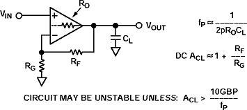
Op amps have an inherent output resistance, Ro, which, in conjunction with a capacitive load, forms an additional pole in the amplifier’s transfer function. As the Bode plot shows, at each pole the amplitude slope becomes more negative by 20 dB/ decade. Notice how each pole adds as much as -90° of phase shift. We can view instability from either of two perspectives. Looking at amplitude response on the log plot,circuit instability occurs when the sum of open-loop gain and feedback attenuation is greater than unity. Similarly, looking at phase response, an op amp will tend to oscillate at a frequency where loop phase shift exceeds -180°, if this frequency is below the closed-loop bandwidth. The closed-loop bandwidth of a voltage-feedback op amp circuit is equal to the op amp’s bandwidth product (GBP, or unity-gain frequency), divided by the circuit’s closed loop gain (ACL).
Continue reading »


